Introduction
Consumer demand for smaller and lighter portable electronic devices continues to require ever smaller batteries of ever increasing charge capacity. This has led to the acceptance of Li-ion technology and the replacement of NiCad and NiMH power sources by rechargeable batteries based upon lithium chemistry.
Putting more and more energy into smaller and lighter containers is clearly a recipe for potential serious safety issues. From the outset of development of batteries with lithium chemistry their thermal stability was questioned and a key feature in the ongoing development programmes over many years has been their safety. Those involved with this work have horror stories of what can happen when batteries are heated and the major fires have been reported occurred in several battery manufacturing facilities.
Test methods for safety of batteries have been devised over many years and there are many tests written into national and international ‘standards’ but generally these tests are empirical and practical. They have also been designed for specific battery types; types that are already in use, not for battery types under development. Tests for thermal stability of batteries have been defined but again, these are simple oven type tests, they do not describe or determine the thermal hazard potential more than just giving an instability temperature.
Manufactures and users of Li-ion batteries appreciate the requirement for thermal safety testing of batteries and their component parts and many realise that more specific and detailed quantitative testing is required if the battery’s safety is to be fully realised.
To determine the stability of the battery, its potential energy release, the speed of energy release and consequence precise thermal measurements are required. Measurement needs to be done under realistic conditions; conditions that can quantify the hazard or truly simulate what might happen in practice.
ARC Testing
Whilst there are a variety of commercial calorimeters available, the Accelerating Rate Calorimeter has been found to be the most appropriate instrument for such safety testing. It has become accepted as a versatile instrument for battery safety testing, because it has several unique or unusual features:
- it has been designed as an adiabatic safety calorimeter
- has high sensitivity
- can accommodate batteries of any size * produces ‘worst case’ thermal data, a
- simulation of a runaway scenario
- allows pressure data to be obtained
- is widely recognised for its reliable thermal data and case of data analysis
The Accelerating Rate Calorimeter is manufactured by Thermal Hazard Technology and to assist battery researchers and manufacturers it has been extensively modified to give greater versatility and flexibility. Battery Safety options have been devised and, to be purpose built for battery safety testing. It has become a Battery Safety Calorimeter.
As such, the THT Accelerating Rate Calorimeter is now used by many major Li-ion battery manufacturers around the world.
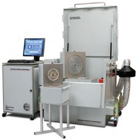
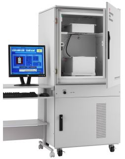
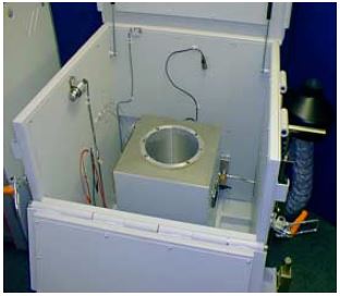
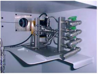
There are two versions of the THT esARC. The standard system (Fig.1) and the EV system (Fig.2). The standard system is suitable for smaller batteries whereas the EV system can be used for much larger cells (Fig.2). The instrument and its technique are simple to describe. The sample is held centrally within the rugged calorimeter assembly (Fig.3).
This calorimeter is 2.5cm thick copper, electroplated with nickel. It houses an array of heaters and thermocouples designed to control separate zones of the calorimeter. The
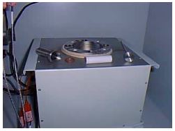
temperature of each zone is referenced against that of the sample. The sample might be a battery of any size and shape, the battery may held within a pressurized container or simply suspended. The sample might be of a component material, e.g. anode or cathode material, electrolyte or mixture; if so the material will be contained in a sealed container.
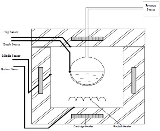
Figure 4 shows a cross section of the calorimeter assembly.
After installing the sample, the blast proof door can be sealed. The door has a safety interlock. The test is programmed and controlled by the PC. The system will heat to the selected start temperature e.g. 50°C. It will then wait to allow isothermal equilibrium to be established, the wait time might be 15 minutes.
The system will then determine if the sample is self-heating. This will be recognised if there is a continuous temperature rise e.g. greater than 0.01°C/min. If there is no temperature rise a heat step is implemented—the heat step might be 3°C. This heat-wait-seek procedure will continue until self-heating is observed.
Figure 5 shows the heat-wait-seek/exotherm method.
When there is a temperature rise faster than the related sensitivity, the system will switch automatically to the ‘exotherm mode’.
The calorimeter operates in the adiabatic mode. This implies no heat loss (or gain) from the sample. When in the exotherm mode the calorimeter temperature will rise as the sample temperature rises. In this adiabatic mode, the worst case is simulated and runaway occurs.
The adiabatic nature of the data means that for any material or sample being tested the data can be scaled to any real life size. Data is stored in terms of time, temperature and pressure.
A full thermal safety test of a battery or component material is completed in the course of a few hours and the data can be interpreted and applied very widely. A most convenient way to represent the data is self-heat rate against time at any temperature before explosion. Other graphical outputs include temperature-time and pressure graphs.
Battery Holders
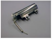
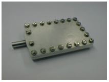
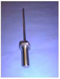
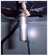
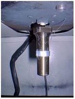
A range of open and closed battery holders have been developed.
Fig 6, 7 show open holders. Fig 8, 9 and 10 show closed holders. Fig 11 shows an 18650 in open configuration and Fig 12 shows an 18650 in closed configuration.
|

|
|

|
|
|
|
The EV ARC
The purpose designed EV, extended volume, ARC is capable of testing much larger cells. The calorimeter is of such a size that it has to be contained in an explosion proof blast chamber. Figure 13 below shows the EV calorimeter within the blast chamber.
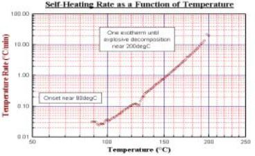
The same tests and procedures that will be described can be carried out in both the standard and extended volume systems. A typical battery test as illustrated here might be of an 18650; it may be tested under any chosen state of charge. Results from a fully charged battery are shown. The self-heating rate result is typical, though for a variety for Li-ion chemistries, the onset of exothermic reaction may be anywhere in the range 85 – 135°C. Figure 14 shows the self-heat rate of a fully charged 18650. Detailed studies on the interpretation of this self- heating have attributed parts of the self heat output to reaction of anode and cathode material.
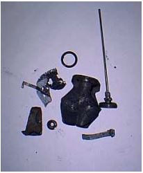
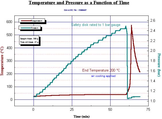
Details discussed of the chemistry is not given here but it can be noted that in all cases the 18650 battery will give a thermal reaction
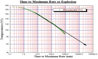
which, if carried out in a sealed container (to obtain pressure data) will lead to a violent explosion of the container (Fig. 15). In normal use, a burst disc protection device is used – though the rugged nature of the Accelerating Rate Calorimeter allows for such explosions to occur and the system is unlikely to be damaged. Also illustrated is the ‘time to explosion’ data for the same test (Fig. 16).
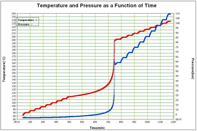
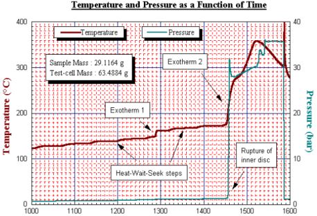
Should the sample reach a specific temperature and held it in ‘no heat loss situation’ this graph shows the time available from this temperature to explosion. A discharged 18650 will show greater stability at lower temperatures though still exhibit a runaway explosion decomposition at higher temperature. The data here is shown on temperature (and pressure) versus time axes. It can be seen that there is a small exotherm near 150°C but then heat steps are put in to raise the temperature to 170°C. From 120°C the major exotherm commenced. Note the pressure data here. Figure 17 shows temperature and pressure data for an undercharged 18650. The standard size calorimeter allows this thermal characterisation of batteries of various styles, from coin batteries, to AA, 4/5A, prismatics of various sizes to 18650’s. These thermal stability tests can be carried out with batteries (or components) on any unmodified Accelerating Rate Calorimeter. However, this is just one type of testing that can be carried out. In addition, the Accelerating Rate Calorimeter can be used to determine the thermal behaviour of batteries and their reaction under conditions of use or abuse. This will provide additionally valuable safety information.
To enable such tests to be carried out, two specific options have been added to the THT Accelerating Rate Calorimeter. The Battery Safety Unit allows abuse conditions to be simulated on a battery within the calorimeter.
The Keisokuki System Unit is a modified single channel battery cycler, this allows charging and discharging cycles to be performed and to simulate use conditions. To carry out these tests, two or four wire connections must be made to the battery sited within the calorimeter. The battery can be held at any chosen start temperature and the test can be completed under adiabatic or isothermal conditions.
Perhaps the simplest scenario that can be simulated within the calorimeter is rapid discharge. When shorting of a charged battery, there will be a fast and large heat release. It is important to quantify this under worst case conditions since batteries held within portable devices might be considered to be within almost adiabatic environments. A key piece of information would be; will the heat that is released show the temperature of the battery sufficient to start the running exothermic reaction that will lead to explosion? For a fully charge Li- ion battery the results indicate that the answer is usually yes. The time profile of the battery being short circuited is illustrated in Fig. 18.
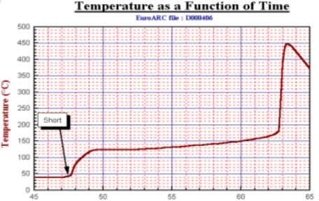
The result shows that it takes 2 minutes for the heat to be fully released and detected but (under the adiabatic conditions) the temperature has risen to 125°C, this is just sufficient for the runaway exothermic reading to start. Almost 15 minutes later the temperature has risen further to 170°C and the battery explodes!
Overcharging with potentially catastrophic thermal effect is a feature of Li-ion batteries. Overcharging (and over-discharging) tests can also be simulated within the THT Accelerating Rate Calorimeter using the Battery Safety Unit option. Results from such tests indicate that different commercial batteries react very differently. This may be due to their chemistry or effectiveness of separator. In a severe overcharging test illustrated here (Fig. 19), a 26650 battery is held adiabatically and connected with pressure measurement and a safety burst disc. Applying 20 volts causes charging and overcharging, this leads self-heating and within 1 hour the battery explodes.
Under normal charge or discharge conditions there is no real safety issue, but there are associated thermal effects. These are small and can easily be quantified by the Accelerating Rate Calorimeter. For this work the Battery Cycling Unit option is used.
The battery is connected within the calorimeter again with 2 or 4 wire measurement. The illustrated data is for a Notebook computer battery pack. The battery was first heated to 40°C, a temperature common in Notebook computers, then constant current discharging at 300m a resulted in self-heating at 6°C/minute (Fig. 20).

The result also shows the voltage drop. The test was discontinued after 50 minutes when the temperature had risen 5°C and the voltage fallen by 0.1V. Discharging will result in self heating of the battery i.e. an exothermic process, charging results in heat absorption i.e. an endothermic process. This is true for fully efficient processes, however, inefficiency in conversion results in exothermicity during charging. For a particular chemistry, such heat output varies with charging rate and age of battery, after long term cycling greater heat output on charging is observed.
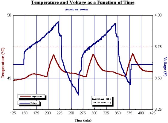
To investigate this batteries can be repeatedly cycled within the THT Accelerating Rate Calorimeter under isothermal conditions. The Battery Cycler Unit option is used. The battery itself is held within an insulating envelope – typically 1–2cm of fibrous ceramic insulation blanket. The battery temperature is continually monitored as the cycling is carried out at a chosen rate, between voltage limits. The cycling may be at constant current to a voltage or the current may be allowed to vary to give a constant voltage. In the data illustrated (Fig. 21), here the increases and decreases in temperature are shown with 2 cycles. After 1,000 cycles, the temperature changes are more exothermic illustrating loss of efficiency of the charging of the battery.
Several further options are available that are useful for more detailed application. One of these is gas collection. Analysis of decomposition products is of importance in development of new chemistries and the System Sampling Unit option (Fig. 22) allows for four gas samples to be taken automatically during any type of test.
Illustrated here are results that aim to show several of the many types of safety and efficiency tests that can be carried out using Accelerating Rate Calorimetry.
Batteries of all shapes and sizes, of all chemistries and at any state of charge may be evaluated and their thermal behaviour quantified. Tests can be carried out with any battery under conditions of use and abuse. In this way the Accelerating Rate Calorimeter is making a vital contribution to battery safety
design.
Thermal Hazard Technology has worked with several battery development and user groups in order to make such technology available and today many larger battery companies have purchased and are using the instrumentation in their development and safety testing. Other organisations come to THT where the equipment can be demonstrated and used on a commercial sample service basis. References are not sited here but for more information visit the website: www.thermalhazardtechnology.com
References :
ARC Technical Information Sheet No. 066, Thermal Hazard Technology, UK
상세한 사항은 아래 첨부된 자료를 참고 부탁 드립니다.
- 22.JPG (26.02kB)
- 8.JPG (11.83kB)
- 3.JPG (15.01kB)
- 9.JPG (12.89kB)
- 18.JPG (41.80kB)
- 17.JPG (58.75kB)
- 16.JPG (25.68kB)
- 2.JPG (42.05kB)
- 19.JPG (49.99kB)
- 10.JPG (13.09kB)
- 5.JPG (68.16kB)
- 11.JPG (13.91kB)
- 12.JPG (14.25kB)
- 20.JPG (48.38kB)
- 15.JPG (15.13kB)
- 2.JPG (18.02kB)
- 6.JPG (11.38kB)
- 1.JPG (18.62kB)
- 13.JPG (20.92kB)
- 14.JPG (25.81kB)
- TIN066 - Application of the ARC for Safety Testing with Li-ion Batteries.pdf (1.58MB)
- 7.JPG (10.32kB)
- 21.JPG (46.01kB)

하기