Ion Milling은 일정 깊이 또는 underlayer까지 물질을 제거하는 데 불활성 가스 (보통 Ar) 이온이 넓은 이온 소스 빔으로부터 진공 내 substrate (또는 코팅된 기재) 표면으로 가속되어 물리적으로 에칭하는 기술이다. 이는 “atomic sandblasting” 또는 더 욱 정확하게는 “ionic sandblasting”으로 볼 수 있다.
Process Pressure Range
|
진공 수준은 통상적으로 10-4 Torr보다 낮으며, 이 때 자유행정거리 (mean free path, MFP)는 이온 소스와 기재 사이의 거리보다 길다. MFP는 원자, 이온, 분자가 진공 챔버에서 다른 입자와 충돌하기 전까지의 평균 거리이다. 이러한 압력 범위는 전형적으로 넓은 빔 이온 소스의 낮은 작동 압력 범위 (1x10⁻⁴ Torr to 5 x 10⁻⁴ Torr)와 같다. 이 범위 이하에서는 이온 빔 소스가 플라즈마(이온의 소스)를 지속시킬 수 없다. |
Energy Transfer
|
이온에 의한 기판의 지속적인 충격은 운동 에너지를 열 에너지로 변환하고 기판의 후속적인 가열을 초래한다. 손상을 방지하도록 기재의 냉각이 필요한 경우가 많다. 입사 이온의 운동 에너지 중 일부는 기판 최상층 원자/원자 클러스터/분자/2차 이온이 표면에서 멀어지게 한다. 기판을 가열하거나 공정 자체로 인해 진공에서 가열되도록 하면, 기판 가열이 표면 입자에 에너지를 더해 더 적은 입사 운동 에너지로 방출되도록 하므로 실제로 에칭 속도를 가속화할 수 있다. 이느 폭주 상태이기 때문에 바람직하지 않을 수도 있다. |
Incident Beam Angles
|
30° ~ 60° 입사 빔 각도는 정상 입사에 비해 에칭 속도를 크게 증가시킨다. 재료에 따라 최대 50%까지 속도가 상승될 수 있다. |
SIMS End point Detection
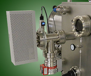
기판 표면의 재료 층에서 나오는 2차 이온이 특정 하층(underlayer)에 도달하는 지 결정할 수 있도록 in-situ로 분석할 수 있습니다. 이 "end point" 검출 기술을 SIMS(Secondary Ion Mass Spectroscopy, 2차 이온 질량 분광법)라고 합니다.
재료 표면부터 에칭되어 상대 강도(relative intensity)가 결정됨으로써 대전입자를 받아들일 수 있도록 검출기가 기판 표면 근처에 장착됩니다. 예: Si 웨이퍼는 100nm의 SiO2로 코팅된 다음 100nm의 Cu로 코팅됩니다.
The top of the Cu is patterned with a photo-resist mask designed to leave behind an array of Cu dots. When the ion milling begins, secondary Cu ions are detected by the SIMS detector as having a significant intensity. As the milling process starts to punch through the Cu top layer and into the SiO2, the intensity of Cu starts to diminish and the presence of SiO2 is first detected and then starts to increase substantially. Eventually the Cu intensity is minimal and the SiO2 intensity is significant. Where the "end point" should be depends on the desired structure. In the case of the Cu dot array it would typically be when the Cu has reached a minimum and is no longer diminishing indicating only the sides of the Cu dots are contributing to the Cu intensity count.
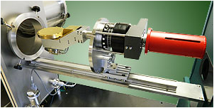
WIDE BEAM ION SOURCES
Gridded DC Ion Sources
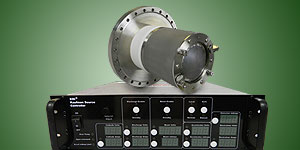
These sources are basically two nested cylinders with a common open end. At the closed end process gas (Ar) is admitted in the proximity of a filament which produces electrons by thermionic emission. These electrons in turn ionize some of the Ar gas atoms.
The open end of the cylinder is fitted with carefully aligned, complementary, electrically isolated grids (typically Mo, W or graphite). Ions are attracted to and will pass through the floating, inner "screen grid" which will develop a small negative potential, the same a sthe plasma potential. As they arrive at the screen grid some ions will pass through/are pushed through the holes of the screen grid. Once these ions pass through the screen grid they immediately pass through an aligned hole in the outer, "accelerator" grid which is at a high positive potential thereby accelerating them away from the source at high energy (e.g. 600 eV).
Typically the inner cylinder (anode) is also at some lower positive potential to prevent sputtering while a multicusp magnet array is used to enhance the ionization efficiency.
As the ions are accelerated in the direction of the substrate they are repelling each other since they are primarily positive ions. As a result the beam diverges as it gets further away from the source. The lower the beam energy, the higher the divergence angle and vice versa. A neutralizing filament is used to add an equal number of electrons to the beam to minimize the divergence and prevent substrate charging. A typical neutralized beam from a source with flat grids has a divergence angle of about 6 o -7o. Concave grids can be used to compensate for this divergence or to focus the beam. Alternatively, convex grids can be employed to create a beam with a wider divergence angle to improve uniformity over a larger area at the expense of current per cm2.
Gridded RF Ion Sources*
RF Gridded source are used for reactive gases (e.g. O2) and are similar to DC sources with a few notable exceptions. They use no filament inside the source and the neutralizer filament is protected within a small can with a hole on one side that is flushed with inert gas to prevent filament burnout from reactive gas use.
Finally they utilize inductively coupled RF power to ionize the gas. The use of reactive gas allows for not only physical etching but also chemical etching via the reactive gas itself. This reactive ion beam etching (RIBE) is particularly useful as anisoptropic structures (having straight sidewalls) can be fabricated and etched material can be volatilized and pumped away vs. simply scattering it in the chamber as with simple, physical ion milling.
RF Sources with a Single Grounded Grid**
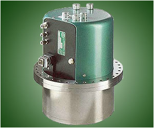
These sources are both capacitively and inductively coupled and deliver moderate currents at comparatively low energy (50-200 eV). They are also referred to as "quasi-neutral" as they emit equal amounts of ions and electrons and thus require no neutralization.
They are useful for mild, low energy milling of delicate substrates and can be used at higher pressures as efficient gas cracking devices.
* These two types of sources are also referred to as "Kaufman sources" after their inventor/developer Dr. Harold Kaufman. The goal of the initial development was for efficient ion thrusters on space vehicles.
**A typical example of such a source is the patented COPRA source developed by CCR Technology.
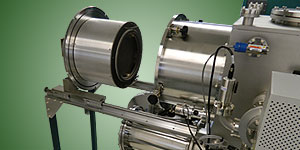
SUBSTRATE HOLDERS FOR ION MILLING
In most cases it is desirable to have a water-cooled substrate holder with tilting (incident angle adjustment for rate maximization) and ideally azimuthal substrate rotation for optimizing uniformity. Other specialty holder have also been developed which introduce reactive gases for RIBE and heated holders which increase rate.
VACUUM PUMPING FOR ION MILLING
It is important to realize that flowing the maximum recommended amount of gas into an ion source will give the highest current output as long as the the vacuum pump is large enough to keep the chamber pressure in the low 10-4 Torr range. The more gas one flows and the larger the ion source is, the larger the vacuum pump needs to be. It is possible to operate a given ion source with an undersized pump but the source's ion current will be compromised.

| 카테고리 | 제목 | 작성자 | 조회수 | |
|---|---|---|---|---|
| E-BEAM EVAPORATION | TUTORIALS FOR ELECTRON BEAM (E-BEAM) EVAPORATION file | YEONJIN | 3537 | TUTORIALS FOR ELECTRON BEAM (E-BEAM) EVAPORATION file |
| THERMAL EVAPORATION | TUTORIALS FOR THERMAL EVAPORATION file | YEONJIN | 2972 | TUTORIALS FOR THERMAL EVAPORATION file |
| SPUTTERING | WHAT IS SPUTTERING? file | YEONJIN | 3364 | WHAT IS SPUTTERING? file |
| ION MILLING | WHAT IS ION MILLING? file | YEONJIN | 3377 | WHAT IS ION MILLING? file |
| 재료시험기 | FINAT Standards | 관리자 | 2045 | FINAT Standards |
| 재료시험기 | PSTC Standards | 관리자 | 2229 | PSTC Standards |
| 재료시험기 | EN Standards | 관리자 | 1733 | EN Standards |
| 재료시험기 | ISO Standards | 관리자 | 2667 | ISO Standards |
| 재료시험기 | ASTM Standards file | 관리자 | 6228 | ASTM Standards file |
| 열전도도측정기 | Fundamentals of measuring λ | 관리자 | 1757 | Fundamentals of measuring λ |
| 열전도도측정기 | 유체의 열전도도 | 관리자 | 1765 | 유체의 열전도도 |
| 점도계 | The QVis Quartz sensor | 관리자 | 1366 | The QVis Quartz sensor |